CONFIGURATION GUIDE
The purpose of the following manual is to describe the necessary configuration of Fortigate equipment for integration with Octopus Platform
| Panel | ||||||||||||
|---|---|---|---|---|---|---|---|---|---|---|---|---|
| ||||||||||||
|
1- Pre-requisites
If there is a firewall in the network that might block the traffic, you will need to allow access to some domains to enable user's authentication:
Radius Servers:
Primary: <IP_Radius_1> 1812 and 1813 UDP ports
Secondary: <IP_Radius_2> 1812 and 1813 UDP ports
Splash Portal server:
Domain <captive_portal_domain> 80 and 443 TCP ports
For the operation of the Guest and Enterprise modules configuration, it will be necessary to previously contract the Octopus platform licenses with the respective modules.
2- Guest module configuration
2.1 Radius Server
The next step is to configure the parameters of the Radius Server to which user authentication requests will be sent. It is recommended to do this through CLI, as part of the configuration is not supported by the graphical interface:
| Code Block | ||
|---|---|---|
| ||
config user radius

    edit Radius_Guest
        set server "<IP_Radius_1>"
        set secret <Secret>
        set acct-interim-interval 600
        set auth-type pap
        set secondary-server "<IP_Radius_2>"
        set secondary-secret <Secret>
        config accounting-server
            edit 1
                set status enable
                set server "<IP_Radius_1>"
                set secret <Secret>
            next
            edit 2
                set status enable
                set server "<IP_Radius_2>"
                set secret <Secret>
            next
        end
	next
    end
|
Then create a user group that uses that server. To do this, go to User & Device > User Groups and add a new group with the following configuration:
| Code Block | ||
|---|---|---|
| ||
config user group
    edit "Radius_Group"
        set member "Radius_Guest"
    next
end
|
2.2 Captive Portal
The next step is to add the VLAN that will be linked to the external captive portal. Go to the section Network > Interfaces and click on Create New Interface to add a new vlan with the following configuration:
Interface Name: type the interface name
Type: VLAN
Interface: select the interface asociated to the VLAN
Address: set up the IP address configuration depending on the client's network parameters.
Administrative Access: RADIUS Accounting
DHCP Sever: set up the DHCP server configuration depending on the client's network parameters.
Admission Control
Security mode: Captive Portal
Authentication Portal: External
Opción http: http://<captive_portal_domain>/login/hotspot/fortigate
Opción https: https://<captive_portal_domain>/login/hotspot/fortigate
User Access: Restricted Groups
User Groups: Select the group containing the Radius Server
Example of configuration by CLI:
| Code Block | ||
|---|---|---|
| ||
config system interface
    edit "vlan710"
        set vdom "root"
        set ip 10.10.0.1 255.255.252.0
        set allowaccess ping radius-acct
        set alias "vlan_Guest710"
        set security-mode captive-portal
        set security-mac-auth-bypass enable
        set security-external-web "https://"<dominio_captive_portal>"/login/hotspot/fortigate"
        set security-groups "Radius_group"
        set role lan
        set snmp-index 14
        set interface "bridgeEth"
        set vlanid 710
    next
end
|
After configuring all the indicated parameters click OK to save the configuration.
2.3 Walled Garden
The next step is to configure the domains that the users will be able to visit without being authenticated in the captive portal. To add each domain name to the walled garden, go to the section Policy & Objects > Addresses and add a new address with the following configuration:
Name: Identifying name
Type: FQDN
FQDN: *domain*
Interface: any
As a minimum they should be added:
<captive_portal_domain>
| Info |
|---|
If you wish to add extra domains (Social Networks, Paypal, etc...) they can be consulted from the following link. |
Example CLI
| Code Block | ||
|---|---|---|
| ||
config firewall address edit "<dominio_captive_portal>" set type fqdn set fqdn "<dominio_captive_portal>" next edit "google-analytics.com" set type fqdn set fqdn "google-analytics.com" next edit "doubleclick.net" set type fqdn set fqdn "doubleclick.net" next end |
Then it is necessary to create an Address Group that includes all of the above domains. To do this, click Create New Address Group and configure the following parameters:
Name:Identifying name
Members: Include all previously added domains.
| Code Block | ||
|---|---|---|
| ||
config firewall addrgrp edit "walledgarden_group" set member "<dominio_captive_portal>" "google-analytics.com" "doubleclick.net" next end |
2.4 Policy
Once all the addresses have been added, it is necessary to associate each one of them to a policy. To do this, go to Policy & Objects > IPv4 Policy and add a series of policies.
walled garden policy
Name: walledgardenpolicy_guest
Incoming Interface: interface created for previous guests.
Outgoing Interface: WAN Interface
Source: all
Destination: indicate the previously added Address Group.
Service: ALL
Action: Accept
The Walled Garden must be bypass so that it is not affected by the configured external captive portal. To do this, access the equipment through the console and execute the following code changing the policy_id for the corresponding one.
| Code Block | ||
|---|---|---|
| ||
config firewall policy
  edit <policy_id>
    set captive-portal-exempt enable
  end
|
DNS Policy
It is also necessary to add a policy allowing access to DNS servers. To do this, add a new policy with the following configuration:
Name: dns_guest
Incoming Interface: previously created interface.
Outgoing Interface: WAN Interface
Source: all
Destination: all
Service: DNS
Action: Accept
Internet Access Policy
To finalize this configuration, an Internet access policy must be created for users authenticated with the following configuration:
Name: auth_guest
Incoming Interface: interface created in the past
Outgoing Interface: WAN Interface
Source:
all
add the previously created Radius group
Destination: all
Service: ALL
Action: Accept
All policies in CLI are summarized below:
| Code Block | ||
|---|---|---|
| ||
    edit 1
        set name "walledgardenpolicy_guest"
        set srcintf "vlan710"
        set dstintf "wan1"
        set srcaddr "all"
        set dstaddr "walledgarden_guest"
        set action accept
        set schedule "always"
        set service "ALL"
        set captive-portal-exempt enable
        set nat enable
    next
    edit 2
        set name "dns_guest"
        set srcintf "vlan710"
        set dstintf "wan1"
        set srcaddr "all"
        set dstaddr "all"
        set action accept
        set schedule "always"
        set service "DNS"
        set captive-portal-exempt enable
        set nat enable
    next
    edit 3
        set name "auth_guest"
        set srcintf "vlan710"
        set dstintf "wan1"
        set srcaddr "all"
        set dstaddr "all"
        set action accept
        set schedule "always"
        set service "ALL"
        set fsso disable
        set groups "Radius_Group"
        set nat enable
    next
end
|
2.5 NAS Identifier
In order for the Radius Server to authorize and identify authentication requests coming from the FortiGate device, it is necessary to modify the name of the device so that it sends the MAC Address of the device. To do this, execute the following commands modifying the MAC address to the corresponding one.
| Code Block | ||
|---|---|---|
| ||
config system global set alias "18CF5EA1F8BD" set hostname "18CF5EA1F8BD" end |
2.6 HTTP or HTTPS login process configuration
There are two configuration options for the validation of the captive portal: One through http connectivity, where the traffic would not be encrypted, and the other through https.
HTTP option
Leaving default values, we can use this configuration.
Normally, the following configuration parameters have nothing configured. Using the command "show" we can verify it:
| Code Block | ||
|---|---|---|
| ||
config user setting show "config user setting end" config firewall auth-portal show "config firewall auth-portal end" |
HTTPS option
The first thing to do is to load a new certificate associated with the subdomain in order to log in. To do so, follow the steps below:
Upload certificate
The first thing to do is to create the certificate in ".pfx" format. We can create it with openssl.
To upload it, go to the System > Certificates > Import > Local Certificate graphical interface:
Type: PKCS #12 Certificate
Certificate with key file: certificate.pfx
Password: leave blank
Certificate Name: <certificate_name>
Configuration changes
| Code Block | ||
|---|---|---|
| ||
config user setting
	set auth-secure-http enable
	set auth-cert <certificate_name>
end

config firewall auth-portal
    set portal-addr <certificate_name>
end
|
Add static DNS entry
If a DHCP server different from the Fortinet device is used, create a DNS entry that resolves "<certificate_name> = interface IP Fortinet portal configuration". Otherwise follow the steps below:
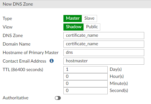
Networks > DNS Servers > DNS Database > Create New
Type: Master
View: Shadow
DNS Zone: <certificate_name>
Domain Name: <certificate_name>
Authoritative: disable
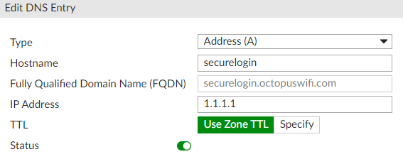
Inside Database created DNS Entries > Create New
Type: Address (A)
Hostname: securelogin
IP Address: include the IP address of the FortiWiFi device in the WIFI interface where the captive portal will be activated. (This IP address can be consulted at Network > Interfaces)
| Code Block | ||
|---|---|---|
| ||
config system dns-database
    edit "<certificate_name>"
        set domain "<certificate_name>"
        config dns-entry
            edit 1
                set hostname "securelogin.<certificate_name>"
                set ip 10.10.0.1
            next
        end
    next
end
|
Verify that the DNS servers delivered to the client is that of the Fortinet. To do this access to Network > Interfaces > WiFi Interface Guests configured > DHCP Server > DNS Server, and configure "Same as IP interface".
2.7 Authorized MAC Addresses
In order to allow the users to authenticate themselves in the captive portal correctly, it is necessary to identify the NAS that will send the authentication requests to the Radius Server. In this case it is necessary to add to the WIFI platform the MAC address previously configured as hostname and alias.
3- Enterprise module configuration
In order to integrate the configurations of this module with the platform, it is necessary to contract the Octopus Wifi Enterprise Module.
3.1 Captive portal + MAC Authentication configuration
To enable MAC authentication it is necessary to edit the vlan associated to the captive portal. To do this it is necessary to access the equipment via SSH or console and execute the following commands indicating the name of the corresponding vlan:
| Code Block | ||
|---|---|---|
| ||
config system interface edit <name> set security-mac-auth-bypass enable next end |
| Info |
|---|
-Validation via MAC address of the devices or MAC Authentication can only be activated if the FortiGate equipment has FortiOS version 6.0.0 or higher. |
3.2 MAC Authentication configuration
To create a dedicated SSID for MAC Authentication validation only, create a firewall policy to allow RADIUS authentication related traffic from the Fortilink interface to the outbound interface on the FortiGate.
| Code Block | ||
|---|---|---|
| ||
config firewall policy
    edit 0
        set srcintf "fortilink-interface"
        set dstintf "outbound-interface-to-RadiusSVR"
        set srcaddr "all"
        set dstaddr "all"
        set action accept
        set schedule "always"
        set service "RADIUS"
        set nat enable
    next
end |
Next, design a RADIUS server and create a user group:
| Code Block | ||
|---|---|---|
| ||
config user radius
      edit "Radius1"
          set server “IP_Radius_1”
          set secret ENC <Secret>
     next
end
config user group
     edit "Radius-Grp1"
         set member "Radius1"
     next
end |
Then in the device configuration interface perform the following configuration:
Go to User & Device > RADIUS Servers and edit or create a new one, add a name and configure the ip/.
Name “IP_Radius_1” y el secret <secret>
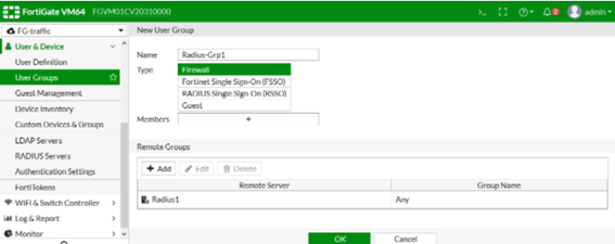
Now go to User & Device > User Groups and create a new group to which the previously created radius server will be added:
A Security Policy must be created using the CLI:
| Code Block |
|---|
config switch-controller security-policy 802-1X edit "802-1X-policy-default" set security-mode 802.1X-mac-based set user-group "Radius-Grp1" set mac-auth-bypass disable set open-auth disable set eap-passthru enable set guest-vlan disable set auth-fail-vlan disable set framevid-apply enable set radius-timeout-overwrite disable next end |
Then in the device interface go to WiFi & Switch Controller > FortiSwitch Security Policy, use the default 802-1X-policy-default or create a new securit policy:
Configure the RADIUS server group created earlier.
Security mode: MAC-based
Click ok
To apply the Security Policy to the device ports perform the following configuration:
| Code Block |
|---|
config switch-controller managed-switch edit S248EPTF1800XXXX config ports edit "port6" set port-security-policy "802-1X-policy-default" next end next end |
3.3 Configuration of Access Profiles
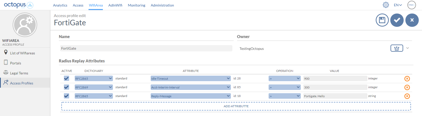
Through the Octopus platform it is possible to configure a series of reply attributes of the Access-Accept packages, grouped in the so-called Access Profile. These Access Profiles allow to activate a series of functionalities in the FortiGate. Although the most common and proprietary FortiGate radius dictionaries are available, the following is a list of some of the most interesting ones:
Attribute | Description | Format |
|---|---|---|
Idle-Timeout | Maximum inactivity time. If the user does not transfer any data on the network during this time, the session will be terminated and the user will have to re-authenticate. | Seconds |
Acct-Interim-Interval | Defines the time interval at which the NAS sends the accounting packet update with all the user's session information. | Seconds (Minimun 600 seconds) |
Reply-Message | Useful for troubleshooting functions, since it allows to identify associated elements of the Octopus platform, such as an access profile, access method, location, ... |
Example of an Access Profile configuration with the attributes explained above:
| Info |
|---|
For more information on how to create an Access Profile in Octopus Platform go to /wiki/spaces/SOP/pages/1963492399 Access profiles |